
I've been working on a DIY Arduboy clone with a larger screen and the ability to load games from a micro SD card. This is probably way too TL;DR for most people, but you can just scroll through and look at the pictures and videos if you want.
Background
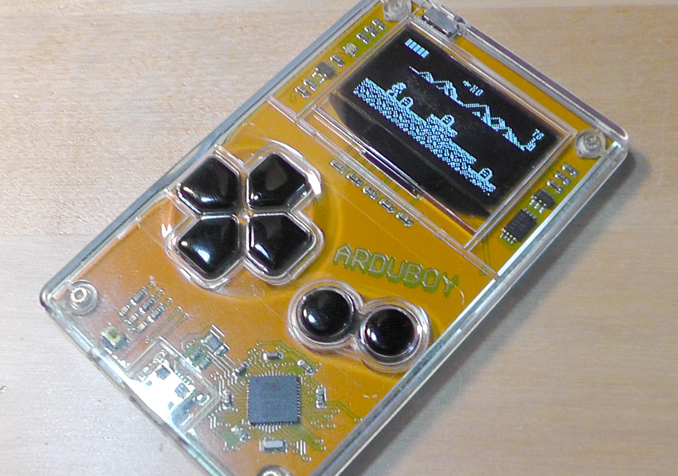
The Arduboy is an arduino based portable game system designed to run free and open source games. It's essentially just an 8-bit microcontroller attached to an oled screen in a credit card sized package.
The harwdare is extremely limited. The processor is a 16MHz ATMega 32u4 with 32KB of flash storage and 2.5KB of RAM. The screen is a 1.3", 128x64 pixel, 1-bit OLED. There are 512 bytes of EEPROM available for save games or high scores. The system can only hold one game at a time and must be reflashed from a PC to switch games.
What's interesting is that this manages to create a somewhat compelling experience with a lot of apparent developer and player appeal. It had a successful kickstarter in 2015, raising more than $400k, and there are more than 100 games for it ranging from first games made by kids to professional looking titles. From a games perspective, this puts it way ahead of other grass-roots console development projects such as the Ouya, which had more than ten times the amount of funding. The success, I think, comes from the limitations - the simple hardware means you need to make a simple game, which makes it easier to get started and easier to finish. And when you're done, the game runs on a completely self contained platform with nothing else to screw it up. If you send your game to a friend, they get exactly the same experience with no real possiblity of malware (although I think you could make a program that would damage the hardware, but it's not like a normal executable where it could ransomware your entire hard drive). Obviously the scope is not the same, but I think a small win is better than a large failure.
My video game hoarding instinct has been activated. I want to have all the games. I have set out to make my own version of the system that has all of the games contained within the system itself, without the need to reflash from a computer.
Research
How do you do this? I know that making an arduino talk to an SD card is fairly straight forward - there are libraries to do it. So we could load files from an SD card, but how do you get them to run on the arduino? There is a small reserved section of program memory called the bootloader, which currently allows you to reprogram the chip via serial communication. Theoretically, this 4KB section of code could be rewritten to reprogram the chip itself from the SD card...
But that sounds really hard. An easier solution is to have a second arduino that talks to the SD card and have it send the program to the game-playing arduino.
The "dual core" design is decided, but how do you make one arduino program another arduino?
Option 1: STK500 over serial
Leveraging the bootloader, you can send serial commands from one arduino to another to reprogram it. This is the same way the computer reprograms the chip when you have it connected via an FTDI usb to serial adapter. For wiring, you just connect the RX->TX and TX->RX (and GND).
I found the following examples:
 Option 2: In Circuit Serial Programmer
This is a more direct programming method using an SPI interface. This method can actually reflash the bootloader itself, which is good because there are more than a few threads out there about how to recover your arduboy when the bootloader screws up. This begs the question of why we have bootloaders to begin with, especially on things like the pro-mini which requires an external device for serial communication. Why not just plug in a different thing and program over the ICSP?
I implemented the following optimizations:
But that sounds really hard. An easier solution is to have a second arduino that talks to the SD card and have it send the program to the game-playing arduino.
The "dual core" design is decided, but how do you make one arduino program another arduino?
Option 1: STK500 over serial
Leveraging the bootloader, you can send serial commands from one arduino to another to reprogram it. This is the same way the computer reprograms the chip when you have it connected via an FTDI usb to serial adapter. For wiring, you just connect the RX->TX and TX->RX (and GND).
I found the following examples:
Arduino Copier by George Caley
I was able to get this code to run on both an Arduino Uno and Pro-Mini, which are both ATMega 328p based boards.
The difficulty is that code is somewhat poorly documented. There are huge blocks of magic numbers, some of which will need to be changed to make the code work for a 32u4 chip. I set about translating the magic numbers into named constants using the STK500 documentation, but the first thing I ran into is a "set device" instruction followed by a device code 0x86 which I could not find listed anywhere. I assume it's the device code for the 328, but I just couldn't find the documentation needed to proceed accurately.
The difficulty is that code is somewhat poorly documented. There are huge blocks of magic numbers, some of which will need to be changed to make the code work for a 32u4 chip. I set about translating the magic numbers into named constants using the STK500 documentation, but the first thing I ran into is a "set device" instruction followed by a device code 0x86 which I could not find listed anywhere. I assume it's the device code for the 328, but I just couldn't find the documentation needed to proceed accurately.
This seems great, it uses named constants and it actually does exactly what I need it to do, even loading the sketch from an SD card. However, I couldn't get it to work. It uses the hardware serial lines to do the programming and a second software driven serial line for debug - I got that hooked up fine but never got more than a few different flavors of error spam. Also there some troll shit like a wiring diagram with a note a few paragraphs down that reads "diagram is wrong" - it makes you question every line of code.
The moral of the story here is to use option 2.
The moral of the story here is to use option 2.
This is a more direct programming method using an SPI interface. This method can actually reflash the bootloader itself, which is good because there are more than a few threads out there about how to recover your arduboy when the bootloader screws up. This begs the question of why we have bootloaders to begin with, especially on things like the pro-mini which requires an external device for serial communication. Why not just plug in a different thing and program over the ICSP?
Hex Uploader (Archive) by Nick Gammon
This worked pretty much immediately, with no difficulties going from one type of arduino to another.
The issue is that it is really slow, taking about 45 seconds to reflash. Some optimizations will be needed.
The issue is that it is really slow, taking about 45 seconds to reflash. Some optimizations will be needed.
-
Removed file length verification. The entire file is read before uploading to avoid going over program memory bounds (essentially reading the file twice). The bootloader area is protected so all that will happen if it does go over is that the upload will fail, so this step seems unnecessary.
-
Removed line checksum validation. Each line in a hex file contains a checksum, but if it's wrong then the file is broken anyway. Where are you getting this file from? Just have good files.
-
Removed clearPage command. I believe this is clearing out the working page on the target chip before uploading new data to it. It takes a long time and not doing doesn't seem to cause any problem. A side effect is that there may be duplicate or garbage data at the end of the last page (the only page that won't be entirely overwritten with new data), but if you end up in that section your program has gone off the rails anyway and you'd just be trying to get a consistent failure state.
If you really need this feature, a better method would be to write 0x00 to the unused portion of only the final page.
-
Reduced/Eliminated BB_DELAY_MICROSECONDS delay. The programming signal goes over a software defined SPI bus, and BB_DELAY_MICROSECONDS is the number of microseconds to hold each clock cycle up or down. The default value is 6, which translates to 83KHz. The SPI bus can go well into the MHz range so increasing this shouldn't be a big deal. I tried 3, then 1, then I replaced the microsecond delay with a few assembly NOP instructions (do nothing for one clock cycle) to delay for less than one microsecond.
Eventually I dialed it down to a single NOP, maximum speed, with no problems.
-
Removed upload verification. Reading back the entire uploaded flash to verify takes a long time. Why not just run it and see what happens?
-
Changed SPI bus initialization SPI_HALF_SPEED -> SPI_FULL_SPEED. Half speed is supposed to avoid errors on a breadboard. I ended up changing back and forth over the course of debugging and didn't notice a difference. I don't think file throughput is the bottleneck here.
-
Added "inline" keyword to BB_SPITransfer(). The bit-bang spi function is now being called millions of times per second, so I figured inlining it could cut out some overhead. I didn't measure any improvement though.
-
Removed chipErase command. Had to undo this one. Turns out you have to erase before writing, you can't just overwrite.
Parts
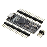
Arduino Micro
Based on the same ATMega 32u4 used in the arduboy, this board breaks out all of the necessary pins to make an exact clone.
It's larger than the pro-micro, but it's good to have a guaranteed test platform.
It's larger than the pro-micro, but it's good to have a guaranteed test platform.
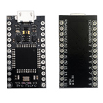
Arduino Pro-Micro
Note that this version has a larger chip package, so it's possible to solder some extra wires directly onto the chip and get full pin compatiblility with the arduboy.
You really need at least three of these - one for the breadboard, one for the final project and one to screw up.
You really need at least three of these - one for the breadboard, one for the final project and one to screw up.
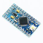
Arduino Pro-Mini
The 328p based pro-mini requires an external usb to serial device to program it, but it's far more reliable than the virtual serial port on the 32u4 based pro-micro.
I ended up using this for the programmer core.
I ended up using this for the programmer core.
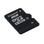
8GB Micro SD Card
Yes, we're going to have a cpu with 2KB of RAM connected to 8GB of storage. Kinda ridiculous, but they don't really make SD cards smaller than this anymore.
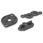
NES Repair Kit
These are for the buttons on the final version. For testing we'll use normal tactile switches.
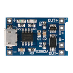
USB Lipo Charger
Notably this also has low voltage cutoff, so it can be used with bare LiPo cells in other projects.
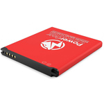
Galaxy S4 Battery
The internet told me that the Samsung Galaxy S4 is the most popular smart phone in the world, so I figured someone would be making new batteries for it. Plus it's a good square shape which is easy to fit in with the other components.
A big problem with buying cell phone batteries is that tons of them are picked out of e-waste bins and sold as new. This one might very well be e-waste with a red sticker on it, but at least they're not trying to pass it off as genuine.
A big problem with buying cell phone batteries is that tons of them are picked out of e-waste bins and sold as new. This one might very well be e-waste with a red sticker on it, but at least they're not trying to pass it off as genuine.
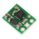
5v Step-Up Voltage Regulator
This will give us a steady 5 volts from a single 3.7v LiPo cell. Note that the voltage regulators on the arduino boards will only regulate down, and require a significantly higher voltage.
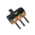
Mini Slide Switch
Rated for 300ma, should be fine. There's also a MOSFET switch for high current applications, but I don't think that will be necessary.
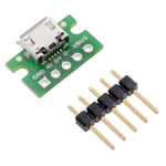
USB Micro-B Breakout
The battery charger has a USB port on it, but if we want a data connection to the arduboy, we can use this breakout first.
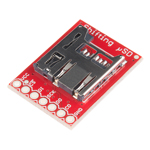
Level Shifting MicroSD Breakout
Built in level shifter converts down to the required 3.3v, has a card detect pin so we can tell when an SD card is inserted.
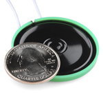
Thin Speaker
Slightly better than a piezo.
0.96" SPI OLED Display
This screen has the exact same SSD1306 controller as the arduboy, and it's cheap, so I got it for testing.
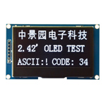
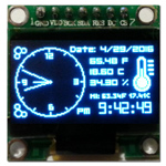
2.42" SPI OLED Display
Nearly twice as big as the default arduboy screen, with a very similar SSD1309 controller. Games can be converted to use this display with some minor hex editing.
Breadboard Clone
It's best to start with duplicating what's already been done before doing something new. I wired up an arduboy clone on the a breadboard using the SSD_1306 screen and a standard piezo, downloaded the source code for a game and compiled it. Everything worked pretty much immediately.
I took that piezo out of a musical birthday card when I was like 10 years old - I knew it would come in handy some day.
I took that piezo out of a musical birthday card when I was like 10 years old - I knew it would come in handy some day.
Enhanced Breadboard Clone
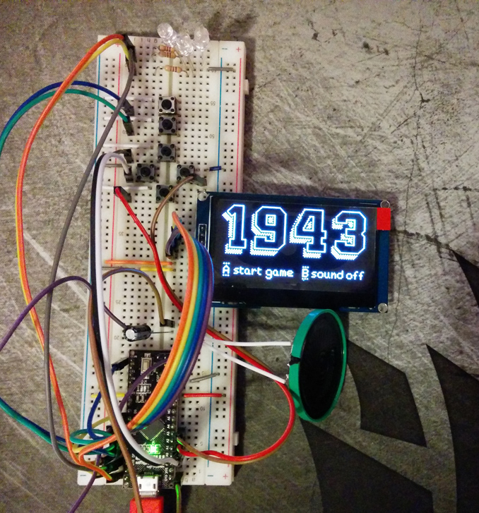
I replaced the screen with the larger SSD_1309 OLED, and the piezo with a speaker. Recompiling the game using the arduboy homemade package and a different screen option worked just fine.
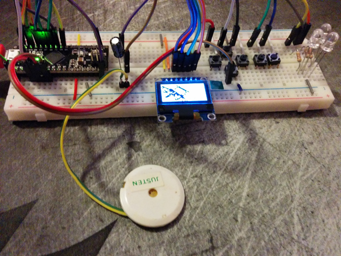
Re-Flash Proof of Concept
This proof of concept build demonstrates that it is possible to switch between two different games without being connected to a computer. The programmer core is on the foreground breadboard with some LEDs for upload status and two dedicated buttons that are hardcoded to upload two different hex files to the arduboy core in the background.
The display and movement buttons are only connected to the arduboy core for simplicity. There is some screen garbage visible when switching games because the screen is on the same bus as the ICSP and the programmer core has no way to turn it off at this point.
The display and movement buttons are only connected to the arduboy core for simplicity. There is some screen garbage visible when switching games because the screen is on the same bus as the ICSP and the programmer core has no way to turn it off at this point.
Full Prototype
Here's a more complicated prototye that shows the entire process working. When power is switched on, the arduboy core boots up normally and starts playing whatever game it has in memory, while the programmer core goes into sleep mode (there's a brief reset hiccup due to some debug code running on the programming core).
Then when you press a dedicated menu button, the programming core wakes up, pulls reset on the arduboy, flips a multiplexer chip to take control of the screen and displays the game menu. It can display an arbitrary number of files in a list with a 64x64 pixel screenshot of each game as you select it.
The programmer core uses a modified version of the SSD1306_text library to display text and graphics. There are more elaborate graphics libraries available, but with the SD card reading and ICSP programming to do, flash space and ram are at a premium. I modified the library to use a custom condensed font with proportional spacing and I wrote a command line utility to convert an png image into the font bytes which could be embedded directly in the arduino sketch.
Normally for displaying a list like this, I would just load the entire thing into ram and be done, but we've only got 2KB of ram and 75% of it is already in use. We don't even have enough to buffer the text that is shown on screen. Also the file system is FAT32, with only support for 8.3 filenames on the arduino. The solution to both of these problems is to have a pre-generated list file containing the short 8.3 hex file name and the longer display name. The entries in the list file are fixed length, so we can easily jump to any line, read it, and print the display name to the screen as we go.
The screenshots are read from separate files and printed to the screen one byte at a time. It's done in sort of a text mode, where 8 pixel high horizontal rows are filled in with vertical stripes (one byte each). I wrote another command line utility that would convert png screenshots to the special format and generate the list file all at once. This way you can keep a collection of game files on your computer with regular long file names and matching screenshots, then just run the utility before uploading everything to the SD card.
Hardware Plans
There are a few more components to finalize: the battery, sound, and RGB LED. I tested the current draw and it maxes out at about 200ma, so I'll probably go with a cell phone battery to ensure a long battery life. The speaker I'm using to test is nice and thin, but it's quite large in diameter, I may shop around for a smaller one. I also need a thumbwheel potentiometer for adjusting the volume, which I've had to resort to ebay for - they don't really make them anymore, all the new stuff uses digital potentiometers which would just complicate things.
The RGB LED on the arduboy is common anode, and as luck would have it all the ones I have lying around are common cathode. I'd like to do some kind of light pipe design around the top or sides of the unit, something to make it more than just a point source. The light pipe on Bezek worked well.
For the buttons, I plan to use rubber domes from an NES controller repair kit (still being made new). I plan to machine the buttons themselves out of aluminum along with the case.
Software Plans
I'd like to be able to cycle between different display modes for the menu by pressing left/right. On one end would be a plain text display with a 1-5 star rating for each game, then the current name/screenshot split, then a full screenshot display. Possibly a title screen display as well.
Some games save high scores or save games to the 512 byte EEPROM. I would like to be able to back up and restore this data when switching games.
Some games save high scores or save games to the 512 byte EEPROM. I would like to be able to back up and restore this data when switching games.
Case Design
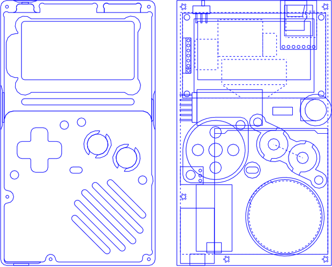
Here's a transparent view showing cutouts for the top part of the case and some internal components. The case is designed to be milled, so inside corners need to be rounded.
It's a somewhat complicated assembly, so I made some models in 3D Studio to make sure everything fits.
It's a somewhat complicated assembly, so I made some models in 3D Studio to make sure everything fits.
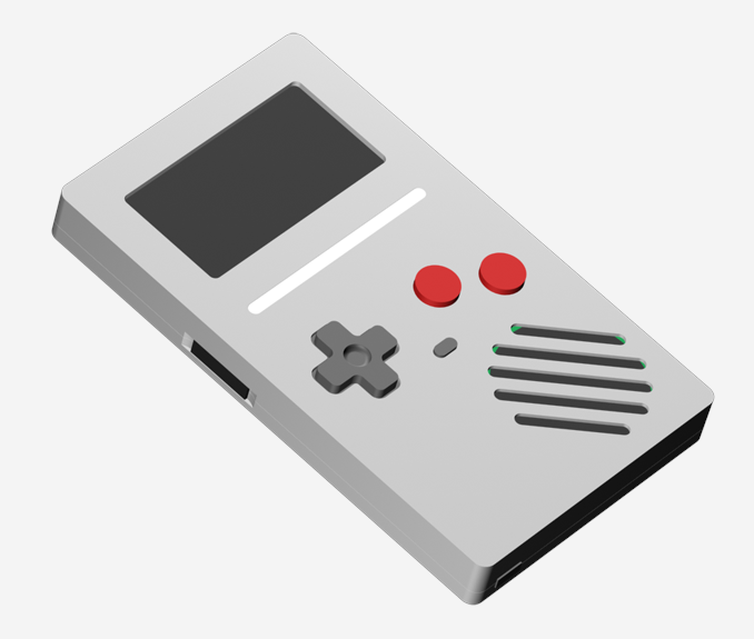
A render of the assembled device. The white bar is a light pipe for the RGB LED.
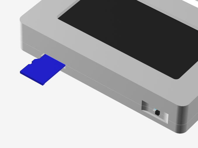
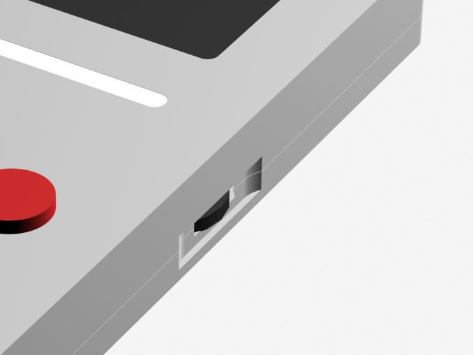
Recessed power switch and micro SD slot.
Volume dial.
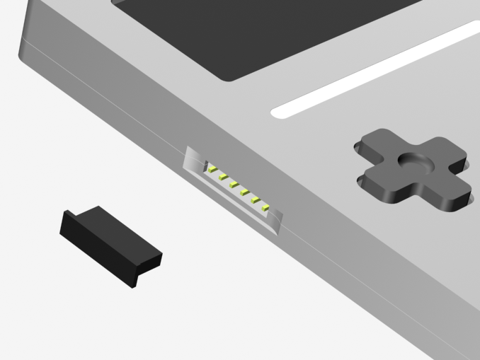
Programming/Debug port and cover.
Assembly animation.
PCB Design
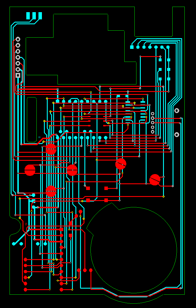
I used DesignSpark PCB to ... design (spark?) the PCB. The trace layout is a mix of manual wiring and auto-router with tweaks afterwards. I found a number of mistakes while double checking everything, hope I found them all!
I exported gerber files and uploaded them to OSHPark for manufacturing.
I exported gerber files and uploaded them to OSHPark for manufacturing.
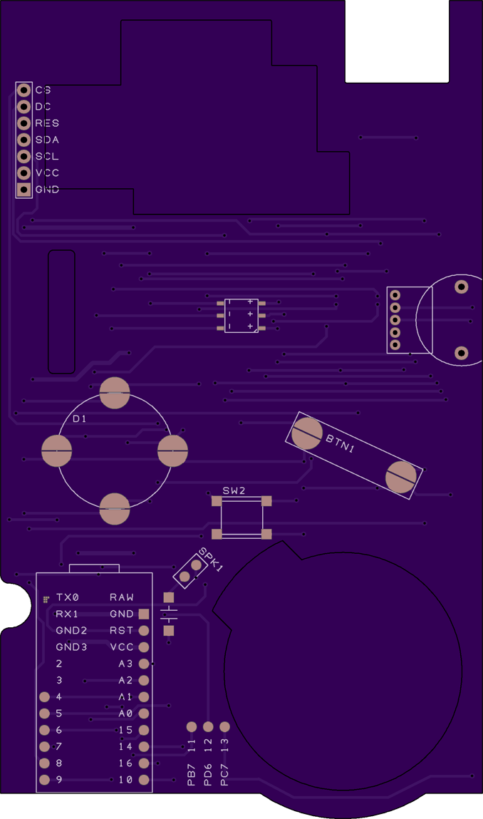
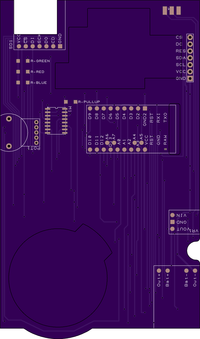
Here are the renders produced by OSHPark's online system. Internal cutouts are shown as black outlines.
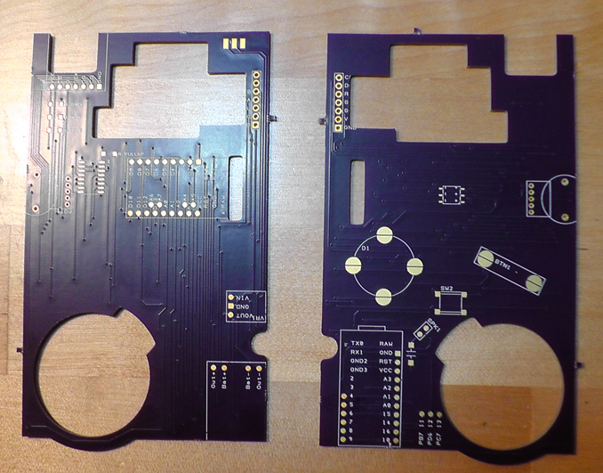
The actual PCBs.
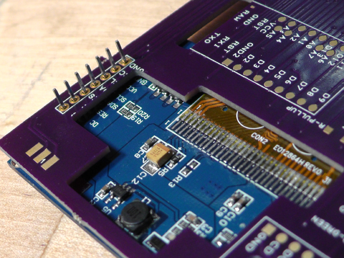
I made one obvious mistake where part of the board blocks some components on the screen module.
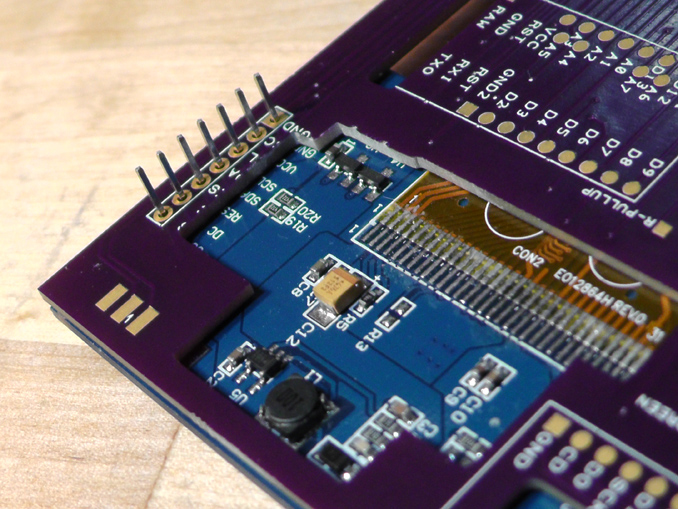
Luckily there are no traces in that part of the board, so a little filing is all it took to fix it.
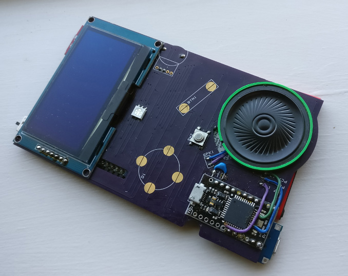
The electronics fully assembled.
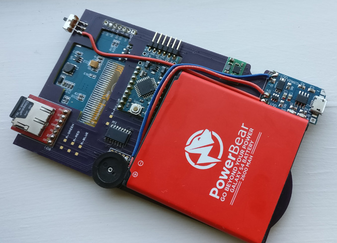
Rear side of the electronics. The battery is designed to be connected with wires, but the wire up to the main switch is a repair due to pads lifting up on the PCB. I should have extended the PCB to support the USB charging module from all 4 corners and glued it down right from the start.
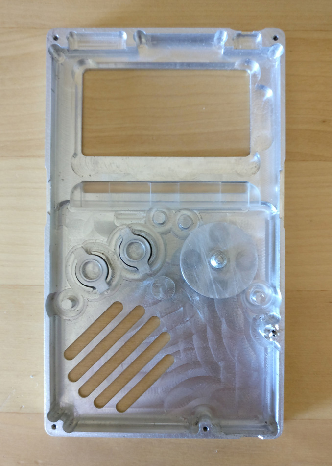
Case Machining
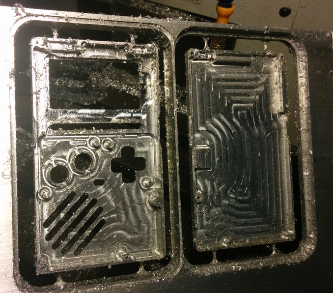
Uhh... long story short I machined a case out of aluminum. I used a Bridgeport V2XT at my local makerspace. It is not an ideal machine for this job because the spindle caps out at 4000rpm - for a 1/8" bit in aluminum you really want 20,000+ rpm to get proper surface speed. There were a few mishaps where the tool holding setup was not secure enough, and on top of that I made a mistake in programming so the D-Pad and menu button holes ended up being too big. It's still passable though.
Naturally, after hours of machining, I broke off the tap inside one of the screw holes. I just left it in there. The remaining screws are enough to hold it together securely.
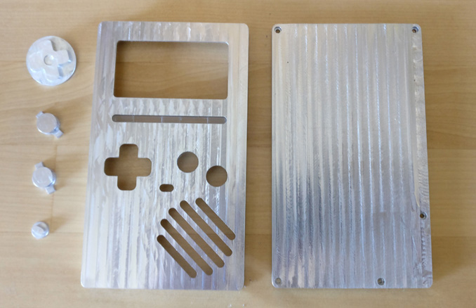
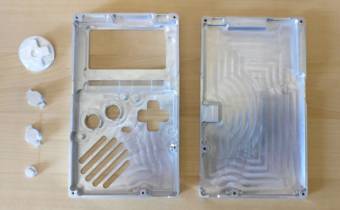
The outside of the case. It's a bit stripey because of vibration. This could have been avoided by using thicker holding tabs or a vise with custom soft jaws. The chattering was particularly bad on the final pass on the right side of the rear panel.
Buttons in place.
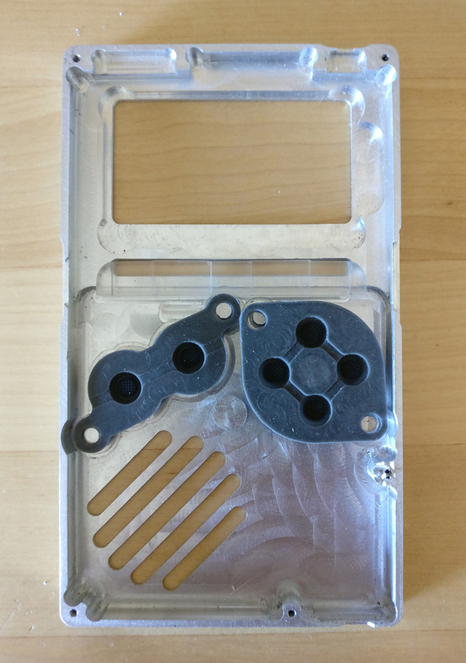
Rubber dome switches from an SNES repair kit.
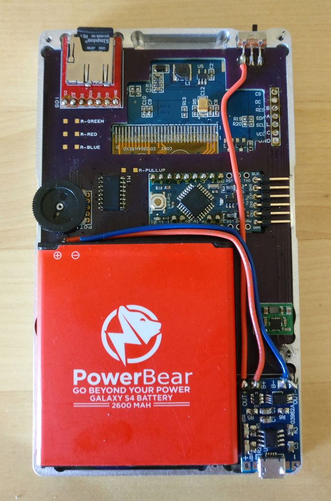
The electronics. Everything fits.
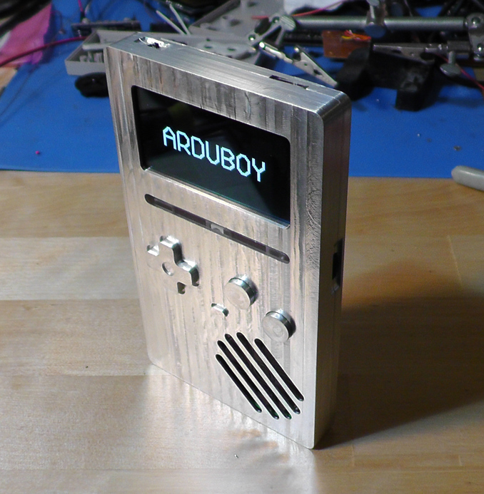
And here it is fully assembled!
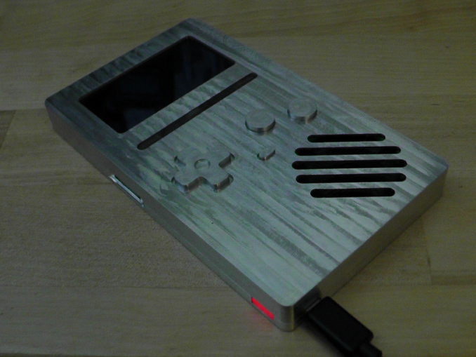
Charging the battery. I made a light pipe out of acrylic that directs the charging status LED to the outside of the case.
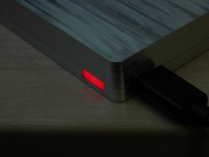
A close up of the light pipe. The light turns blue when the battery is fully charged.
Files
The zip contains the ICSP flasher arduino project, the C++ binaries and source for converting the screenshots, PCB files, and STL files for the case and buttons.
Comments
2018-06-14 22:11:26
coolio
you should come back to blockland
SPRITE2018-06-22 20:47:06
Really love the animation, what did you use to make it?
Badspot2018-06-22 21:58:28
3D Studio Max
egg2018-07-09 04:00:48
good job. i like this
i also feel bad for badspot, always bothered about his goddamn game
i also feel bad for badspot, always bothered about his goddamn game
bice
A L E M2018-07-31 11:37:18
Neato!
It looks like the buttons on the case are part of the case itself, meaning that they cant be pressed???
It looks like the buttons on the case are part of the case itself, meaning that they cant be pressed???
Badspot2018-07-31 18:38:04
I assure you they are separate parts and can be pressed. They are both made out of aluminum though.
johnnyws2018-08-02 08:12:30
hey badspot can I be unbanned from the forums yet
LeetZero2018-08-09 05:44:49
How much different do actual aluminium buttons feel compared to plastique controllers?
Sir Blockhead2018-08-15 13:16:40
HOW COULD YOU FORGET BLOCKLAND?!?!?!?
YOU LEFT IT INTO DARKNESS!!!
YOU LEFT IT INTO DARKNESS!!!
Fazza2018-08-15 20:38:46
epic epic
CRAZEY2018-08-16 15:16:49
can you make a video of you playing some games on it?
Easy2018-08-24 21:23:24
Every thought about porting blockland to Switch? Not saying it would be easy but would be a easy way to make the game blowup again
Superfun909/wilrnilr2018-09-05 21:30:14
That..actually sounds like a really good idea, though, torquescript might be really hard to port, and I think badspot is just done with blockland content updates.
Hostileuser2018-09-07 00:15:34
Real cool, man. If only my shaky hands could do something this talented.
Brick Braydon2019-03-24 19:06:30
@Badspot please join bl my users Brick Braydon im new and really want to see the creator of bl :)
Brick Braydon2019-03-24 19:06:31
@Badspot please join bl my users Brick Braydon im new and really want to see the creator of bl :)
badspot abandoned bl, he's not gonna join you lol
Chazpelo2020-01-02 19:37:21
badspot doesn't care about blockland lol
just play it without baddy, lol,
or just do drama on BLG updates.
just play it without baddy, lol,
or just do drama on BLG updates.
marmita2020-11-06 17:21:51
what is the pinout of this arduboy
uwu2021-11-26 00:07:02
BADSPOT PLS PORT BLOCKLAND TO THE ARDUBOY
can the arduboy enlarge my penis?2023-02-27 19:48:20
please badspot add this feature